I N S T A L L A T I O N E N C A S T R E E - DCS WD1-30-SSOD - Manuel d'utilisation - Page 11

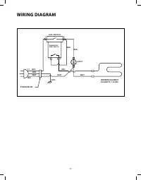

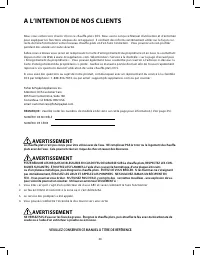

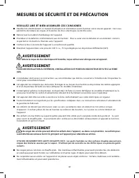
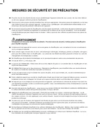
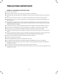
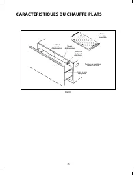
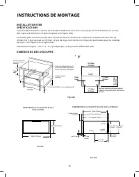
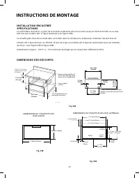
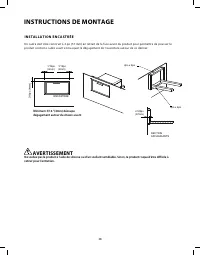
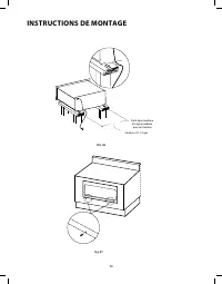
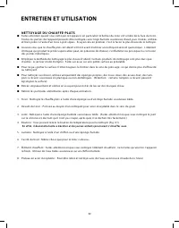
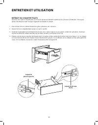
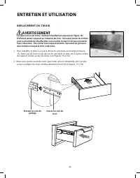

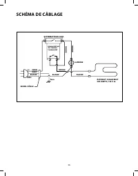


Table des matières:
- Page 4 – A L’INTENTION DE NOS CLIENTS; AVERTISSEMENT; VEUILLEZ CONSERVER CE MANUEL À TITRE DE RÉFÉRENCE.
- Page 5 – TABLE DES MATIÉRES
- Page 6 – MESURES DE SÉCURITÉ ET DE PRÉCAUTION; V E U I L L E Z L I R E E T B I E N A S S I M I L E R C E S C O N S I G N E S
- Page 8 – P R I È R E D E C O N S E R V E R C E S I N S T R U C T I O N S; PRÉCAUTIONS IMPORTANTE
- Page 9 – CARACTÉRISTIQUES DU CHAUFFE-PLATS
- Page 10 – INSTRUCTIONS DE MONTAGE; I N S T A L L A T I O N F I E R; D I M E N S I O N S D E S D E C O U P E S
- Page 11 – I N S T A L L A T I O N E N C A S T R E E
- Page 12 – I N S T A L L A T I O N E N C A S T R É E
- Page 15 – ENTRETIEN ET UTILISATION; R É G L A G E S D E T E M P É R A T U R E; MISE EN GARDE; S É L E C T E U R D E T E M P É R A T U R E :
- Page 16 – N E T T O Y A G E D U C H A U F F E - P L A T S
- Page 17 – R E T R A I T D U C H A U F F E - P L A T S
- Page 18 – R E P L A C E M E N T D U T I R O I R
- Page 19 – RÉGLAGES DE TEMPÉRATURE; T E M P É R A T U R E S S U G G É R É E S P O U R G A R D E R L E S A L I M E N T S C H A U D S
- Page 20 – SCHÉMA DE CÂBLAGE
- Page 21 – P O U R L’O B T E N T I O N D E S E R V I C E :
Prise
électrique
installé
support
16”
23 1/4po (590mm)
26 1/8po (663mm)
24 1/8po (613mm)
1 1/8po (28mm)
11-11/16po
(297mm)
12-1/4po
(311mm)
13/16po
(20mm)
1po(25mm)
30”
14 -7/16po
(367mm)
1 -5/8po
(41mm)
ÉGOUT
DIMENSIONS DU CHAUFFE-PLATS (VUE LATÉRALE)
28
27
I N S T A L L A T I O N E N C A S T R E E
S P É C I F I C A T I O N S
La profondeur du boîtier, à partir de la bordure extérieure de la face avant jusqu’au fond du boîtier ou au mur,
doit mesurer 614mm (24 3/16po) minimum (voir figure 02B).
Le chauffe-plats doit être installé dans un boîtier dont les dimensions extérieures minimum doivent être de
470mm (18 1/2po) de haut sur 787mm (31po) de large sur 614mm (24 3/16po) de profondeur pour les modèles
de 30 po. (voir figure 03B et figure 04B).
Alimentation requise : 120 V c.a., 15 A minimum protégée par un disjoncteur différentiel (GFI).
2-1/2” min. to
bottom of
countertop
30 3/16po
(766mm)
16 3/16po
(411mm)
30 3/16po
(766mm)
21 1/8po
(537mm)
2 3/4po
(70mm)
2 3/4po
(70mm)
ENCASTREE
Position soutenir planches comme
indiqué si le produit peut être fixé en
position.
26 3/16 po (664mm) min.
profondeur d'armoire
6,35cm (2 /1/2 po) min.
jusqu'au bas du dessus
de comptoir
Une prise d'alimentation CA
de 120 volts doit être située
au-dessous du chauffe-plats
2x4 ou support
similaire
16 3/16po (411mm)
Fig. 02B
Fig. 03B
Fig. 04B
D I M E N S I O N S D E S D E C O U P E S
INSTRUCTIONS DE MONTAGE
CORDON
D’ALIMENTATION
ÉGOUT
40,6cm (16 po)
72,23 cm (28-7/16 po)
66,04 (26 po)
60,17 cm (23-11/16 po)
29,69 cm (11-11/16 po)
7,62cm (30 po)
31,12 cm
(12-1/4 po)
DIMENSIONS DU CHAUFFE-PLATS
(VUE AVANT)
„Téléchargement du manuel“ signifie que vous devez attendre que le fichier soit complètement chargé avant de pouvoir le lire en ligne. Certains manuels sont très volumineux, et le temps de chargement dépend de la vitesse de votre connexion Internet.
Résumé
20 A L’INTENTION DE NOS CLIENTS Nous vous remercions d’avoir choisi ce chauffe-plats DCS. Nous avons conçu ce Manuel d’utilisation et d’entretien pour expliquer les fonctions uniques de cet appareil. Il contient des informs extrêmement utiles sur la façon cor- recte de faire fonctionner votre nouvea...
22 21 TABLE DES MATIÉRES M E S U R E S D E S É C U R I T É E T D E P R É C A U T I O N 22 C A R A C T E R I S T I Q U E S D U C H A U F F E - P L A T S 25 I N S T R U C T I O N S D E M O N T A G E Specifications 26 Montage et installation 29-30 E N T R E T I E N E T U T I L I S A T I O N Reglages de...
22 MESURES DE SÉCURITÉ ET DE PRÉCAUTION V E U I L L E Z L I R E E T B I E N A S S I M I L E R C E S C O N S I G N E S n Veuillez lire attentivement ce manuel d’utilisation et d’entretien avant d’utiliser votre nouvel appareil. Ceci vous permettra de réduire les risques d’incendie, de chocs électriq...