Maytag MGDZ600TK2 - Manuels
Maytag MGDZ600TK2 - Guide de dépannage en ligne au format PDF.
Manuels:
Guide de dépannage Maytag MGDZ600TK2
Résumé
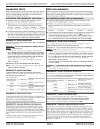
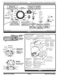
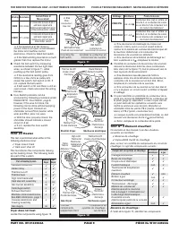
FOR SERVICE TECHNICIAN ONLY - DO NOT REMOVE OR DESTROY POUR LE TECHNICIEN SEULEMENT - NE PAS ENLEVER NI DÉTRUIRE PART NO. W10133923A PAGE 2 PIÈCE N o W10133923A DIAGNOSTIC TESTS These tests allow factory or service personnel to test and verify allinputs to the machine control electronics. You may wa...
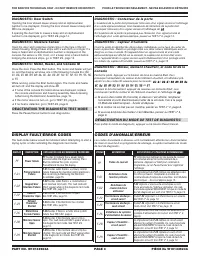
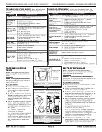
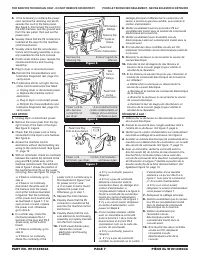
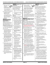
FOR SERVICE TECHNICIAN ONLY - DO NOT REMOVE OR DESTROY POUR LE TECHNICIEN SEULEMENT - NE PAS ENLEVER NI DÉTRUIRE PART NO. W10133923A PAGE 3 PIÈCE N o W10133923A DIAGNOSTIC: Door Switch Opening the door should cause a beep and an alphanumericnumber to be displayed. Closing the door should cause a bee...
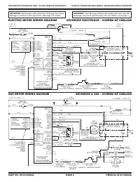
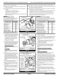
FOR SERVICE TECHNICIAN ONLY - DO NOT REMOVE OR DESTROY POUR LE TECHNICIEN SEULEMENT - NE PAS ENLEVER NI DÉTRUIRE PART NO. W10133923A PAGE 4 PIÈCE N o W10133923A P8-2 P8-2 2M 1M 5M 6M 3M T TAN LBU BU CL W BL BU-W BU-BL P8-4 P8-3 P9-1 P8-5 BK-W N-BL 4M MTR CS MTR CC P13-1 P13-2 P14-4 P14-5 P14-3 P14-6...
Maytag Manuels
-
 Maytag MRT711SMFB00
Manuel d'utilisation
Maytag MRT711SMFB00
Manuel d'utilisation
-
 Maytag MDB8969SDE0
Manuel d'utilisation
Maytag MDB8969SDE0
Manuel d'utilisation
-
 Maytag MEW9627FW01
Manuel d'utilisation
Maytag MEW9627FW01
Manuel d'utilisation
-
 Maytag MDB4949SDH3
Manuel d'utilisation
Maytag MDB4949SDH3
Manuel d'utilisation
-
 Maytag MEDX6STBW1
Manuel d'utilisation
Maytag MEDX6STBW1
Manuel d'utilisation
-
 Maytag MVWC416FW0
Manuel d'utilisation
Maytag MVWC416FW0
Manuel d'utilisation
-
 Maytag MSB26C6MDE02
Manuel d'utilisation
Maytag MSB26C6MDE02
Manuel d'utilisation
-
 Maytag MVWB835DC5
Manuel d'utilisation
Maytag MVWB835DC5
Manuel d'utilisation
-
Maytag MVWB835DC5
Notice d'Installation
-
 Maytag 4KMVWC215FW0
Manuel d'utilisation
Maytag 4KMVWC215FW0
Manuel d'utilisation
-
Maytag MEW9627FZ01
Manuel d'utilisation
-
 Maytag MVWB765FW2
Manuel d'utilisation
Maytag MVWB765FW2
Manuel d'utilisation
-
Maytag MEW9527FB00
Manuel d'utilisation
-
Maytag MEW9530FZ01
Manuel d'utilisation
-
Maytag MEW9530FB01
Manuel d'utilisation
-
 Maytag 4KMVWC405BW0
Notice d'Installation
Maytag 4KMVWC405BW0
Notice d'Installation
-
 Maytag 4KMVWC300BW0
Notice d'Installation
Maytag 4KMVWC300BW0
Notice d'Installation
-
Maytag MEW9530FB00
Manuel d'utilisation
-
Maytag MDB6949SDH0
Manuel d'utilisation
-
Maytag MVWB865GW0
Manuel d'utilisation