Haier HCW3460AES - Notice d'Installation
Haier HCW3460AES - Notice d'Installation, à lire gratuitement en ligne au format PDF. Nous espérons que cela vous aidera à résoudre toutes les questions que vous pourriez avoir. Si vous avez encore des questions, contactez-nous via le formulaire de contact.
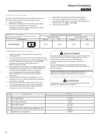
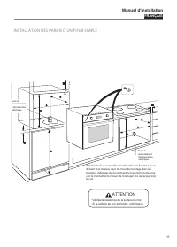
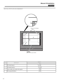
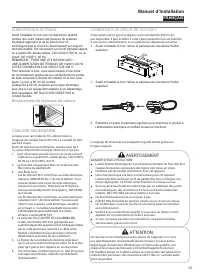
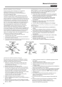


Table des matières:
- Page 1 – ELECTRICAL CONNECTIONS; FINAL CHECKLIST; FRANÇAIS; TABLE DES MATIERES; AVERTISSEMENT
- Page 2 – RISQUE D’ÉLECTROCUTION LIÉ À LA MISE À LA TERRE; OUTILS NÉCESSAIRES; Manuel d’Installation
- Page 3 – REMARQUES SUR L’INSTALLATION; FOUR SIMPLE; SIMPLE; Position du four (distance par rapport au; INSTALLATION DES PAROIS D UN FOUR SIMPLE; Vérifiez la résistance de la surface du mur.; ATTENTION; DONNÉES TECHNIQUES
- Page 4 – Vérifie z la résistance de la surface du mur.
- Page 5 – INSTALLATION EN ALIGNEMENT; Lettre; Découpe profondeur; fils cuivre ou aluminium.
- Page 6 – Emplacement de la plaque de valeurs
- Page 7 – ESPAÑOL; TABELA DE CONTENIDO; ATENCIÓN; INTRODUCCIÓN; BRANCHEMENT ÉLECTRIQUE
- Page 8 – RIESGO DE CHOQUE ELÉCTRICO CONEXIÓN; Manual de Instalación
- Page 11 – Do Not Return This Product To The Store; IMPORTANT; Ne pas Réexpédier ce Produit au Magasin; IMPORTANTE; No regrese este producto a la tienda; Italy; Printed in
ENGLISH
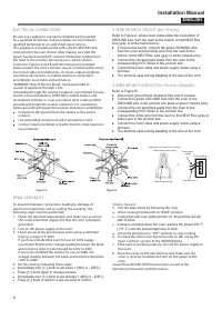
ELECTRICAL CONNECTIONS
Be sure your appliance is properly installed and grounded
by a qualified technician. Ask your dealer to recommend a
qualified technician or an authorized repair service.
This appliance is manufactured with a green GROUND wire
connected to the oven chassis. After making sure that the
power has been turned off, connect the flexible conduit from
the oven to the junction box using a U.L. listed conduit
connector. Figures A and B and the instructions provided
below present the most common way of connecting the ovens.
Your local codes and ordinances, of course, take precedence
over these instructions. Complete electrical connections
according to local codes and ordinances
“WARNING” Risk of Electric Shock, frame grounded to
neutral of appliance through a link
.
Grounding through the neutral conductor is prohibited for new
branch-circuit installations (1996 NEC); mobile homes; and
recreational vehicles, or in an area where local codes prohibit
grounding through the neutral conductor. For installations
where grounding through the neutral conductor is prohibited:
Disconnect the ground from the neutral at free end of
conduit;
Use grounding terminal or lead to ground unit; and
Connect neutral terminal or lead to branch circuit neutral in
usual manner.
Figure A
Figure B
FINAL CHECKLIST
To prevent improper connections leading to damage of
electrical components and so voiding the warranty, the
following steps must be performed:
1. Check the electrical requirements and make sure you have
the correct electrical supply and that the oven is properly
grounded.
2. Turn on the power supply to the oven.
3. Check power at the junction box wires using a voltmeter
having a range of 0-250V.
If you have installed the oven for use on 240V supply,
you should find that the voltage reading between the black
and red wires (Line to Line) should be 220V to 240V.
If you have modified the oven(s) for use on 208V, the
voltage reading between the black and red wires should be
190 to 208V.
4. Set the clock by following these steps:
Clock is now set.
5. Test the bake mode by following this step:
Move cooking mode knob to “BAKE” position.
Move the knob back to “OFF” position to stop cooking.
6. To check the other oven functions refer to the “Using the
Oven Controls” section of the USER MANUAL.
7. If the oven is working properly, turn off the power supply to
the oven.
8. Place the cover on the junction box and make sure the
cover is securely fastened and turn on the power to the
oven.
Leave these INSTALLATION instructions as well as the
V
Operating Instructions with the owner.
3-WIRE BRANCH CIRCUIT (for US only)
4-WIRE BRANCH CIRCUIT (for US and CANADA)
FRANÇAIS
TABLE DES MATIERES
page
page
page
n
o
it
c
u
d
o
r
t
n
I
Remarques sur l’installation
Connexion à un circuit de
120 V/
208 V
13
Outils nécessaires
Branchement électrique
14
Alimentation requise
Conne
14
Choix de l’emplacement du four
9
Installation en alignement
12 Conne
14
Alimentation électrique
13 Liste de vérification finale
14
Données techniques
Câblage nécessaire
13
AVERTISSEMENT
Si l’information de ce manuel n’est pas suivie exactement,
cela peut provoquer un incendie ou une explosion
pouvant entraîner des dégâts, des blessures ou la mort.
INTRODUCTION
Vous aurez besoin des outils suivants pour installer votre
nouveau four :
Mètre enrouleur et règle à tracer ou règle
Crayon
Tournevis Philips
Niveau
Cutter de
électriques et dénude-
Scie sauteuse ou scie à main
Scie-cloche de 1 po (2,5 cm)
Mèche et perceuse
Gants et lunettes de sécurité
Voltmètre (0-250 V AC)
EMBALLAGE
Enlevez tous les adhésifs et emballage avant d’utiliser le four.
Détruisez tous les emballages après avoir désemballé le four
en suivant les règles d’usage de votre ville. Ne laissez jamais
les enfants jouer avec les emballages.
ALIMENTATION REQUISE
Le four doit être alimenté avec la fréquence et la tension
appropriée . Le four est fabriqué pour être branché à une
alimentation électrique triphasée ou à quatre
en simple
phase,
120 V/
des deux côtés de la ligne. Si un circuit de
120 V/
208 V doit être
utilisé, voyez Connexion à un circuit de
120 V/
208 V dans ce
manuel. Un disjoncteur ou un dispositif de surcharge dont la
taille n’excède pas la valeur du circuit de l’appareil spéc
sur
la plaque de valeurs située sur le cadre derrière la porte du
four est recommandé (voir
à la page 12).
Il est recommandé que vous ayez un branchement électrique
parfaitement raccordé par un électricien qual
Après tout avoir installé, l’électricien doit vous montrer où est
le débranchement principal et quels sont le disjoncteur et les
fusibles pour le four.
CHOIX DE L’EMPLACEMENT DU FOUR
Choisissez précautionneusement l’emplacement du four.
Le four doit être situé pour un usage approprié dans la cuisine,
mais toujours loin des courants d’air.
Les courants d’air peuvent être provoqués par des portes
ouvertes ou des fenêtres, ou par des ventilateurs ou l’air
conditionné. Assurez-vous que le branchement peut arriver
jusqu’à l’emplacement choisi.
Le four ne doit être branché qu’avec des fils de cuivre ou aluminium.
Si un câble en aluminium est fourni pour la connection du four au
circuit électrique, il est nécessaire utiliser les connecteurs énumérés
par UL. Suivez les instructions fournies avec les connecteurs.
IMPORTANT :
Gardez ces instructions pour consultation par l'inspecteur local des
INSTALLATEUR :
Veuillez laisser ce manuel au propriétaire pour de futures références.
Veuillez garder ce manuel pour de futures références.
9
9
Installation des parois d'un four simple
9
10
10
11
240 V, 60 Hz CA sur un circuit séparé avec fusibles
10
s
installations électriques.
●
Immediately turn [+/-] knob to set hours + [INC] or - [DEC] .
●
Press [+/-] knob again to change minutes.
●
Immediately turn [+/-] knob to set minutes + [INC] or - [DEC] .
●
Press [+/-] knob or wait for a few seconds to confirm.
●
Cooling fan and oven lights will turn on, the preheat led will
start to blink.
●
A beep is sounded when the oven reaches the preset 350 °F
(175 °C) and the preheat light stop to blink.
Refer to Figure A, where local codes allow the connection of
GROUND wire from the oven to the branch circuit NEUTRAL
wire (gray or white colored wire):
● If local codes permit, connect the green GROUND wire
from the oven and the white wire from the oven to the
branch circuit NEUTRAL wire (gray or white colored wire).
● Connect the red and black leads from the oven to the
corresponding HOT Wires in the junction box.
● Connect the local codes and power supply codes using a
terminal.
● The terminal uses a thing adapting to the wire of the cord.
Refer to Figure B:
● Disconnect ground from neutral at free end of conduit.
● Connect the green GROUND wire from the oven to the
GROUND wire in the junction box (bare or green colored wire).
● Connect the red and black leads from the oven to the
corresponding HOT Wires in the junction box.
● Connect the white wire from the oven to the NEUTRAL (gray or
white) wire in the junction box.
● Connect the local codes and power supply codes using a
terminal.
● The terminal uses a thing adapting to the wire of the cord.
From power
supply
From the oven
Terminal Block
Square-wire spring
Important: Use twist-on connector
with square-wire spring
Or
8
ENGLISH
Installation Manual
„Téléchargement du manuel“ signifie que vous devez attendre que le fichier soit complètement chargé avant de pouvoir le lire en ligne. Certains manuels sont très volumineux, et le temps de chargement dépend de la vitesse de votre connexion Internet.
Résumé
ENGLISH ELECTRICAL CONNECTIONS Be sure your appliance is properly installed and grounded by a qualified technician. Ask your dealer to recommend a qualified technician or an authorized repair service. This appliance is manufactured with a green GROUND wire connected to the oven chassis. After making...
ENGLISH ELECTRICAL CONNECTIONS Be sure your appliance is properly installed and grounded by a qualified technician. Ask your dealer to recommend a qualified technician or an authorized repair service. This appliance is manufactured with a green GROUND wire connected to the oven chassis. After making...
FRANÇAIS REMARQUES SUR L’INSTALLATION 1. Ne faites pas glisser le four par terre. Vous pourriez abîmer par terre. 2. La surface du support du four doit être une plate-forme de contreplaqué d’au minimum 2 cm (3/4 po) d’épaisseur. Pour les fours simples, elle doit supporter 202 livres (92 kg). La plat...