Big Ass Fans MK-I61-051800A729S2 - Manuel d'utilisation - Page 6
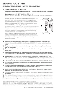
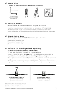
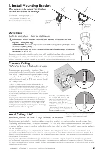
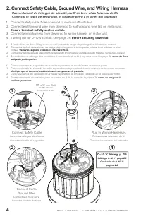
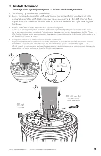
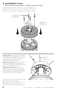
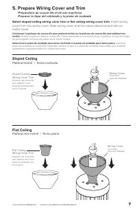
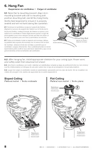
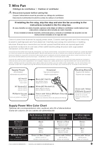
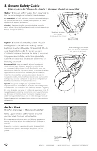
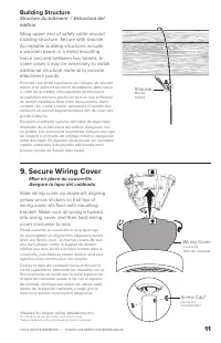
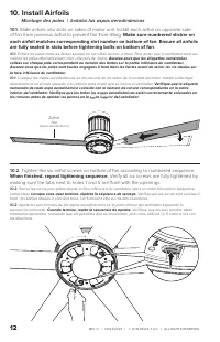
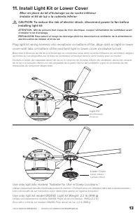
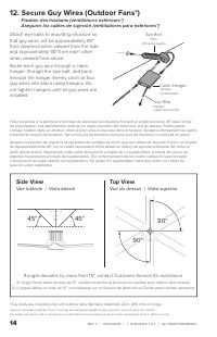
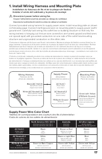
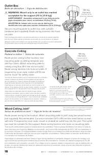
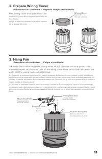
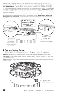
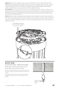
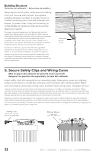
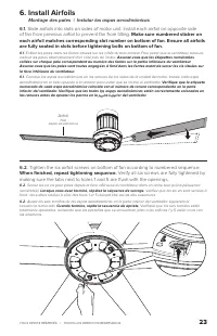
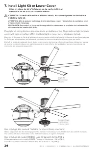
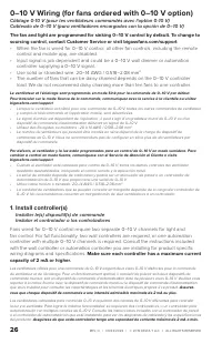
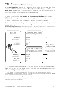
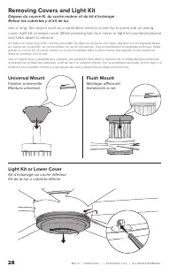

Table des matières:
- Page 2 – BEFORE YOU START; AVANT DE COMMENCER | ANTES DE COMENZAR; ☑ Turn off Power at Breaker
- Page 3 – ☑ Gather Tools; Préparez les outils nécessaires | Busque las herramientas; ☑ Check Outlet Box; Revisar la sección sobre cableado de 0–10 V (opcional); If you are wiring the fan for; sourcing; –10 V control, review the instructions on; ☑ Check Ceiling Slope; Vérifiez la pente du plafond | Verificar la pendiente del techo; Maximum Ceiling Slope: 33°
- Page 4 – Concrete Ceiling; Plafond en béton | Techo de concreto; Outlet Box; Boîte de dérivation | Caja de distribución; Install Mounting Bracket
- Page 5 – Ground Wire
- Page 7 – Install Motor Cover; Mise en place du cache moteur | Instalar la cubierta del motor; Motor Cover
- Page 8 – Prepare Wiring Cover and Trim; Insert wiring; Sloped Ceiling; Plafond incliné | Techo inclinado; Flat Ceiling; Plafond non incliné | Techo plano
- Page 9 – Raise fan to mounting bracket. Align rib in; Power wires; Suspension du ventilateur | Colgar el ventilador
- Page 10 – Câblage du ventilateur | Cablear el ventilador; Supply Power; Australia; Supply Power Wire Color Chart
- Page 11 – Secure Safety Cable; Anchor Hook; Crochet d’ancrage | Gancho de anclaje
- Page 12 – Secure Wiring Cover; Building Structure; Shackle
- Page 13 – Montage des pales | Instalar las aspas aerodinámicas; of fan from previous airfoil to prevent fan from tilting.; Make sure numbered sticker on; When fi nished, repeat tightening sequence.; Verify all six screws are fully tightened by
- Page 14 – Install Light Kit or Lower Cover; Use only light kits marked “Suitable for Use in Damp Locations.”
- Page 15 – Top View; Vue du dessus | Vista superior; Side View; Vue latérale | Vista lateral
- Page 17 – Install Wiring Harness and Mounting Plate; Disconnect power before wiring fan.
- Page 18 – Wiring
- Page 19 – Prepare Wiring Cover; Préparation du couvre-fi ls | Preparar la tapa del cableado
- Page 20 – Ensure terminal is; Secure Safety Cable
- Page 22 – Secure Safety Clips and Wiring Cover; Safety Clip; Structure du bâtiment | Estructura del edifi cio
- Page 24 – Install Light Kit or Lower Cover
- Page 26 – –10 V Wiring (for fans ordered with 0–10 V option); controller supplying a 0–10 V signal.; Make sure each controller has a maximum current
- Page 27 – Câbler le ventilateur | Cablear el ventilador; Route 0–10 V wiring into downrod and connect to 0–10 V wires; before securing downrod to fan; Route 0–10 V wiring through mounting plate and connect to 0–10 V; Fan 0–10 V Input Channel
- Page 28 – Removing Covers and Light Kit; Universal Mount
TOUS DROITS RÉSERVÉS.
|
TODOS LOS DERECHOS RESERVADOS.
5
3. Install Downrod
Montage de la tige de prolongation | Instalar la varilla separadora
1. Tuck wiring up into bottom of downrod.
2. Lower downrod onto motor shaft, aligning yellow arrow sticker on downrod with
arrow tab on motor shaft. Make sure wires are protruding 2–3 in. (51–76 mm) from
top of downrod. Insert nut into left side of downrod and bolt into right side. Tighten
hardware.
1. Rentrez les fi ls dans la partie inférieure de la tige de prolongation.
2. Abaissez la tige de prolongation sur l’arbre moteur en alignant l’étiquette jaune avec une fl èche noire
de la tige de prolongation sur celle de l’arbre moteur. Assurez-vous que les fi ls dépassent de 51 à 76 mm
(2 à 3 po) en haut de la tige de prolongation. Insérez l’écrou du côté gauche de la tige de prolongation et la
vis du côté droit. Serrez le boulon.
1. Coloque los cables en la parte inferior de la varilla separadora.
2. Baje la varilla separadora hasta el eje del motor, alineando la etiqueta con la fl echa amarilla de la varilla
separadora con la pestaña amarilla del eje del motor. Verifi que que los cables sobresalgan 2–3 in.
(51–76 mm) de la parte superior de la varilla separadora. Inserte la tuerca en la parte izquierda de la varilla
separadora y el perno en la parte derecha. Ajuste los accesorios.
M6 x 36 mm Bolt
Vis M6 × 36 mm
Perno M6 x 36 mm
M6 Nut
Écrou M6
Tuerca M6
1
2
2 –3 in.
(51–76 mm)
„Téléchargement du manuel“ signifie que vous devez attendre que le fichier soit complètement chargé avant de pouvoir le lire en ligne. Certains manuels sont très volumineux, et le temps de chargement dépend de la vitesse de votre connexion Internet.
Résumé
REV. O | 09/22/2022 | © 2019 DELTA T LLC Ι ALL RIGHTS RESERVED. WARNING: Installation must be in accordance with the requirements set forth by the National Electrical Code (NEC, United States), ANSI/NFPA 70, and all national and local codes.The ground wire must be connected to the supply grou...
TOUS DROITS RÉSERVÉS. | TODOS LOS DERECHOS RESERVADOS. 1 ☑ Gather Tools Préparez les outils nécessaires | Busque las herramientas Provided with fan Fourni avec le ventilateur Provisto del ventilador ☑ Check Outlet Box Vérifiez la boîte de dérivation | Verificar la caja de distribución Mount to...
TOUS DROITS RÉSERVÉS. | TODOS LOS DERECHOS RESERVADOS. 3 Concrete Ceiling Plafond en béton | Techo de concreto Route power wiring to fan location. Use mounting bracket as drilling template and drill four holes. Attach mounting bracket to ceiling using four Ø 6 mm anchor bolts*. If required by loca...
Autres modèles de ventilateurs de plafond Big Ass Fans
-
 Big Ass Fans FR127C-U1H00-3L00-09258-258P61
-
Big Ass Fans FR127C-U1H00-3L00-09259-259P61
-
 Big Ass Fans FR127C-U1H00-3L0209258-532P610
-
Big Ass Fans MK-HK4-04240001A258F221G10
-
Big Ass Fans MK-HK4-04240001A258F222G10
-
Big Ass Fans MK-HK4-04240001A259F221G10
-
Big Ass Fans MK-HK4-04240001A470F221G10
-
Big Ass Fans MK-HK4-04240001A470F222G10
-
Big Ass Fans MK-HK4-04240001A471F221G10
-
Big Ass Fans MK-HK4-04240001A471F222G10